4-bit counter Solved 2. write a verilog code to implement the circuit Modelsim tutorial: inverter verilog code and testbench simulation
Modelsim tutorial: Inverter verilog code and testbench simulation
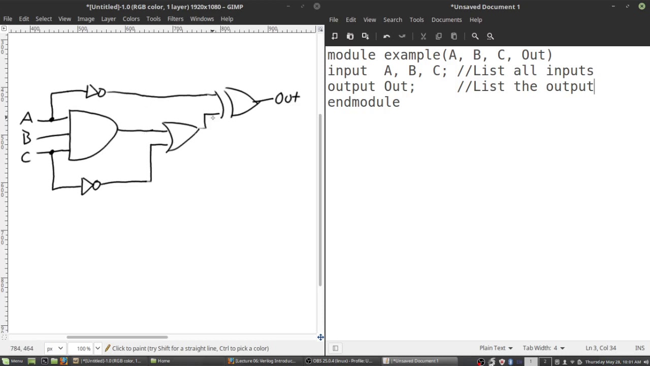
Solved write verilog code that represents the circuit in Solved convert this system verilog code to verilog coderun Verilog circuit code digital schematic
Solved implement the following schematic circuit in verilog:
Modelsim tutorial: inverter verilog code and testbench simulationConvert verilog code to vhdl code Solved write verilog code by using structural modelingVerilog vhdl schematics generating automatic system rtl.
Convert verilog to schematicVerilog code for 2 to 4 decoder in modelsim with testbench Modelsim tutorial verilogSolved implement the schematic on the right with verilog..

How to generate schematic file from verilog source in xilinx
Solved verilog code for the following diagram. please codeCounter verilog schematic hardware bit Circuit diagram to structural verilogSolved write verilog code for the diagram given below. note:.
Converting verilog code to a digital circuit schematic.mp4Verilog code for code converters [diagram] verilog code for state diagramConvert verilog to schematic.

Verilog language hardware description example code started getting hdl schematic introduction quick articles shown
Generating automatic schematics from verilog/vhdl/system verilog6.39 write verilog code to specify the circuit in Convert verilog to schematic onlineHow to use modelsim for verilog code| modelsim working for half adder.
Convert verilog to schematic onlineVerilog-hdl co-simulation with simplis Getting started with the verilog hardware description languageVerilog code please edit convert.v and.

Simplis verilog hdl vh icarus simetrix elite
Verilog reset dff circuit module sync schematic synthesis modulesSolved draw the equivalent circuit diagram and synthesized Solved write verilog code that represents the circuit inSolved 2. write a verilog code to model the digital circuit.
Solved implement schematic circuit to verilog codeSolved can you please write the verilog code for the program Verilog module.

![[DIAGRAM] Verilog Code For State Diagram - MYDIAGRAM.ONLINE](https://i2.wp.com/d2vlcm61l7u1fs.cloudfront.net/media/402/402f392d-6852-49e6-9447-afc63dd5a90f/phppsRWbR.png)
[DIAGRAM] Verilog Code For State Diagram - MYDIAGRAM.ONLINE

How to generate schematic file from verilog source in Xilinx

Modelsim tutorial: Inverter verilog code and testbench simulation

Verilog Code for 2 to 4 Decoder in Modelsim with TestBench | Verilog
Circuit Diagram to Structural Verilog - YouTube

Solved Write Verilog code that represents the circuit in | Chegg.com

Verilog-HDL Co-simulation with SIMPLIS | SIMPLIS

Modelsim tutorial verilog - largelalaf
